Category:IC pinout diagrams
Jump to navigation
Jump to search
Deutsch: Pinbelegungsdiagramme von integrierten Schaltungen.
· English: Integrated circuits (ICs) pinout diagrams.
· Nederlands: Aansluitschema's (pinconfiguraties) van geïntegreerde schakelingen
· Русский: Цоколёвки интегральных схем (ИС)
· Deutsch: Diese Kategorie ist nur für Pinout-Diagramme von ICs gedacht (siehe Kategorienname). Funktionsdiagramme gehören hierher. Bilder von ICs gehören hierher. Alle Diagramme in dieser Kategorie sollten im SVG-Format vorliegen.
English: This category is for pinout diagrams of ICs only. Functional diagrams belong here. Pictures of ICs belong here. All diagrams in this category should be SVG.
Nederlands: Deze categorie is alleen voor ic-pinconfiguraties. Voor functieschema's is er de categorie: IC functional diagrams, en voor foto's: Close-ups of integrated circuits. Het SVG-formaat heeft de voorkeur voor alle schema's in deze categorie.
Русский: Эта категория предназначена исключительно для цоколёвок ИС. Для функциональных диаграмм используется категория IC functional diagrams, для изображений самих ИС — Close-ups of integrated circuits. Для рисунков в этой категории желательно использовать формат SVG.
Media in category "IC pinout diagrams"
The following 200 files are in this category, out of 239 total.
(previous page) (next page)-
2114 pinout.svg 158 × 204; 11 KB
-
4000 Pinout.svg 220 × 220; 38 KB
-
4001 Pinout.svg 220 × 220; 54 KB
-
4002 Pinout.svg 220 × 220; 50 KB
-
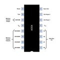
4004 dil.png 1,024 × 1,024; 42 KB
-
4004 dil.svg 830 × 810; 34 KB
-
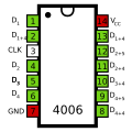
4006 Pinout.svg 220 × 220; 43 KB
-
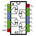
4007 Pinout.svg 220 × 220; 46 KB
-
4008 Pinout.svg 220 × 240; 39 KB
-
4011 Pinout.png 460 × 441; 11 KB
-
4011 Pinout.svg 220 × 220; 65 KB
-
4012 Pinout.svg 220 × 220; 48 KB
-
4013 Pinout.svg 220 × 220; 34 KB
-
4014 Pinout.svg 220 × 245; 50 KB
-
4015 Pinout.svg 220 × 245; 52 KB
-
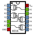
4016 Pinout.svg 220 × 220; 39 KB
-
4017 Pinout.svg 220 × 240; 38 KB
-
4017-chip.png 250 × 300; 57 KB
-
4018 Pinout.svg 220 × 240; 38 KB
-
40192 Pinout.svg 350 × 240; 38 KB
-
40193 Pinout.svg 350 × 240; 38 KB
-
4020 Pinout.svg 220 × 240; 37 KB
-
4021 Pinout.svg 220 × 240; 68 KB
-
4022 Pinout.svg 220 × 240; 66 KB
-
4023 Pinout.svg 220 × 220; 76 KB
-
4024 Pinout.svg 220 × 220; 67 KB
-
4025 Pinout.svg 220 × 220; 79 KB
-
4026-chip.png 250 × 300; 57 KB
-
4027 Pinout.svg 220 × 240; 37 KB
-
4046 Pinout.svg 338 × 238; 67 KB
-
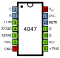
4047 Pinout.svg 230 × 220; 34 KB
-
4049 Pinout.svg 220 × 240; 44 KB
-
4050 ic.png 392 × 399; 16 KB
-
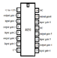
4050 Pinout.svg 220 × 240; 43 KB
-
4060 pinout.png 640 × 500; 32 KB
-
4060 Pinout.svg 220 × 240; 37 KB
-
4066 Pinout.svg 220 × 220; 39 KB
-
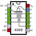
4068 Pinout.svg 220 × 220; 53 KB
-
4070 Pinout.svg 220 × 220; 61 KB
-
4071 Pinout.svg 220 × 220; 57 KB
-
4072 Pinout.svg 220 × 220; 48 KB
-
4073 Pinout.svg 220 × 220; 74 KB
-
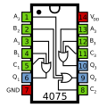
4075 Pinout.svg 220 × 220; 77 KB
-
4077 Pinout.svg 220 × 220; 62 KB
-
4081 Pinout.svg 220 × 220; 55 KB
-
4082 Pinout.svg 220 × 220; 50 KB
-
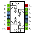
4093 Pinout.svg 220 × 220; 66 KB
-
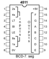
4511-chip.png 250 × 300; 57 KB
-
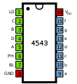
4543 Pinout.svg 220 × 240; 37 KB
-
555 Pinout.svg 220 × 145; 7 KB
-
6264 SRAM Pinout.svg 99 × 170; 6 KB
-
6510 CPU Pinout.svg 113 × 230; 9 KB
-
6522 VIA Pinout.svg 113 × 227; 9 KB
-
6526 CIA Pinout.svg 113 × 237; 10 KB
-
6532 RIOT Pinout.svg 113 × 230; 9 KB
-
7360 pinout.png 747 × 1,321; 14 KB
-
7360 pinout.svg 396 × 624; 3 KB
-
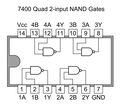
7400 Quad 2-input NAND Gates.PNG 1,000 × 900; 71 KB
-
7400 vs 4011.png 2,167 × 3,247; 22 KB
-
7401 pinout.svg 720 × 558; 22 KB
-
7402 Quad 2-input NOR Gates.PNG 1,000 × 900; 74 KB
-
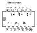
7404 Hex Inverters.PNG 1,000 × 900; 69 KB
-
7404 pinout.jpg 472 × 594; 25 KB
-
7407 Hex Buffer.png 1,000 × 778; 58 KB
-
7408.jpg 274 × 186; 15 KB
-
741 pin assignment 01 Pengo.svg 800 × 400; 14 KB
-
7414 pinout.jpg 472 × 594; 26 KB
-
7486 Quad 2-input ExOR Gates.PNG 1,000 × 900; 70 KB
-
74HC02 pinout.jpg 472 × 594; 27 KB
-
74LS30.png 300 × 353; 8 KB
-
8085 microprocessor Presentation.pdf 1,500 × 1,125, 30 pages; 1.61 MB
-
8085-PIN-1.png 417 × 491; 7 KB
-
8216 8226 Pinout.png 575 × 719; 33 KB
-
8250 and 16450 UART.svg 350 × 520; 62 KB
-
8255.svg 306 × 527; 18 KB
-
8282 Pinout.png 414 × 584; 5 KB
-
8283 Pinout.png 388 × 590; 6 KB
-
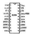
8286 8287 Pinout.png 758 × 556; 20 KB
-
8288 Pinout.png 515 × 606; 5 KB
-
8X300.PNG 480 × 880; 26 KB
-
A QFP28 Template.svg 588 × 588; 5 KB
-
A QFP44 Template.svg 515 × 515; 7 KB
-
Anschlussbelegung 8085.gif 583 × 730; 14 KB
-
Anschlussbelegung 8085.svg 872 × 904; 5 KB
-
AT89C1051.png 165 × 139; 3 KB
-
Atari ANTIC (CO12296) pin-out.svg 202 × 400; 60 KB
-
Atari FREDDIE.svg 360 × 527; 27 KB
-
Atari GTIA (CO14805) pin-out.svg 202 × 400; 61 KB
-
Atari POKEY.png 301 × 157; 19 KB
-
Atari POKEY.svg 202 × 400; 59 KB
-
ATmega328P 28-PDIP.svg 710 × 422; 43 KB
-
Atmega8 pinout.svg 638 × 213; 71 KB
-
AY-3-8500 pinout.png 538 × 509; 23 KB
-
AY-3-8550 pinout.png 620 × 446; 20 KB
-
AY-3-8610 chip pinout.svg 512 × 471; 13 KB
-
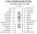
AY-3-8610 pinout.png 458 × 421; 14 KB
-
AY-3-8910 pinout.JPG 700 × 620; 59 KB
-
Brochage 16F84.jpg 300 × 212; 30 KB
-
Brochage 74125.png 513 × 430; 23 KB
-
Brochage 74LS51.png 513 × 430; 20 KB
-
Brochage des circuits logiques 74184 et 74185.png 513 × 430; 17 KB
-
Brochage des circuits logiques 74595 et 74596.png 512 × 430; 22 KB
-
C8231A FPU PIN CONFIGURATION.png 589 × 561; 47 KB
-
Ci7400.svg 190 × 242; 24 KB
-
Ci7401.svg 190 × 242; 24 KB
-
Ci7402.svg 190 × 242; 24 KB
-
Ci7403.svg 190 × 242; 24 KB
-
Ci7404.svg 190 × 242; 26 KB
-
Ci7408-7409.svg 190 × 242; 22 KB
-
Ci7410.svg 190 × 242; 23 KB
-
Ci7411.svg 190 × 242; 21 KB
-
Ci7413.svg 190 × 242; 23 KB
-
Ci7414.svg 190 × 242; 29 KB
-
Circuit AT89LV51 pini configuratie.png 446 × 416; 39 KB
-
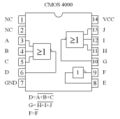
CMOS 4000.JPG 687 × 684; 57 KB
-
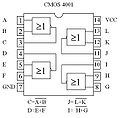
CMOS 4001.JPG 654 × 643; 61 KB
-
CMOS 4002.JPG 665 × 626; 57 KB
-
CMOS 4011 diagram.svg 320 × 448; 5 KB
-
CMOS 4049 diagram.svg 320 × 480; 6 KB
-
CMOS 4071 diagram.svg 320 × 448; 5 KB
-
CMOS 4081 diagram.svg 320 × 448; 4 KB
-
CMOS XOR pinout.png 513 × 430; 22 KB
-
Configuratie pini atmel at89c52.jpg 559 × 566; 75 KB
-
Configuratie-pini-505.png 739 × 678; 54 KB
-
CP1600 PIN.png 550 × 770; 30 KB
-
CSG 65CE02.png 215 × 370; 312 KB
-
Diagrama pini AT89c5130A 2.PNG 364 × 427; 20 KB
-
Diagrama pini AT89c5130A 3.PNG 350 × 336; 14 KB
-
Diagrama pini AT89c5130A.PNG 386 × 404; 19 KB
-
DIP28 with Pin Numbers.svg 512 × 2,240; 11 KB
-
DM7402.svg 70 × 100; 1 KB
-
DM74LS266.svg 70 × 100; 1 KB
-
EF9345P pinout.png 300 × 534; 39 KB
-
Eprom1702pinout.png 392 × 274; 5 KB
-
Generic 741 pinout top.png 1,346 × 600; 29 KB
-
Generic 74XX TTL IC.PNG 127 × 226; 3 KB
-
GenericIC.svg 210 × 304; 5 KB
-
GI CP1600.png 240 × 370; 348 KB
-
HEF4067B-pinout.jpg 423 × 148; 16 KB
-
I8085 Buses.JPG 692 × 397; 28 KB
-
Intel 4004 processor pinout.png 1,109 × 669; 100 KB
-
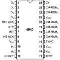
Intel 4040 processor pinout.png 985 × 990; 99 KB
-
Intel 8041 pinout.png 355 × 634; 25 KB
-
Intel 8080 Microprocessor.png 898 × 1,636; 145 KB
-
Intel 8080 Pinout.svg 709 × 850; 31 KB
-
Intel 8086 pinout.svg 399 × 604; 86 KB
-
Intel 8087.svg 360 × 520; 58 KB
-
Intel 8089.svg 360 × 520; 58 KB
-
Intel 8237.svg 400 × 530; 57 KB
-
Intel 8253 and 8254.svg 320 × 330; 36 KB
-
Intel 8259.svg 310 × 390; 37 KB
-
Intel 8284.svg 320 × 330; 28 KB
-
Intel i8086 pinout.svg 590 × 1,052; 105 KB
-
Intel M8282 y M8283.png 1,121 × 631; 298 KB
-
Isl2901.jpg 245 × 213; 41 KB
-
LM317 TO-220.svg 176 × 462; 10 KB
-
LM324N Operational Amplifier.png 1,283 × 1,171; 19 KB
-
LM324N Operational Amplifier.svg 600 × 530; 3 KB
-
Lm358.gif 239 × 146; 3 KB
-
LM4663 Pinout.jpg 332 × 298; 17 KB
-
LM741 Pinout Round.svg 250 × 150; 19 KB
-
LM741 Pinout Square-it.svg 300 × 145; 24 KB
-
LM741 Pinout Square.svg 300 × 145; 30 KB
-
MAX232 Pinout.svg 220 × 245; 50 KB
-
MC145151-2.svg 296 × 388; 25 KB
-
MC6845.svg 381 × 527; 28 KB
-
Mc6847.png 383 × 682; 12 KB
-
Microcontroller 16F628A.PNG 1,307 × 781; 69 KB
-
Microcontroller 8051.gif 750 × 323; 49 KB
-
MOS 6501.png 215 × 370; 312 KB
-
Mos 6508.png 215 × 370; 312 KB
-
MOS 6560 pinout.svg 576 × 1,152; 9 KB
-
Mos 7501.png 215 × 370; 14 KB
-
MOS 8566 VIC-IIe pinout.png 313 × 623; 30 KB
-
MOS6502.svg 306 × 527; 24 KB
-
MOS6526.svg 265 × 528; 23 KB
-
MOS6581.svg 301 × 383; 20 KB
-
MOS8502.svg 306 × 527; 9 KB
-
Motorola 6800.png 215 × 370; 312 KB
-
National Semiconductor INS8900 CPU pinout.svg 815 × 760; 7 KB
-
National Semiconductor PACE CPU pinout.svg 815 × 760; 7 KB
-
NE555 Symbol.svg 836 × 496; 15 KB
-
NE556 pennen.svg 220 × 230; 28 KB
-
NE558 pennen.svg 220 × 260; 32 KB
-
NE612 Blockschaltbild.svg 525 × 400; 17 KB
-
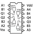
NOR Pinout.jpg 451 × 460; 110 KB
-
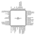
NXP LPC2148 pinout.svg 706 × 706; 8 KB
-
PCF8574 Pinout.svg 220 × 240; 37 KB
-
PCX8582x Family.png 1,818 × 928; 26 KB
-
PIC16F84 brochage.png 622 × 359; 21 KB
-
Pic16F876.png 1,176 × 627; 80 KB
-
Piedinatura del MOS 6507.jpg 180 × 224; 12 KB
-
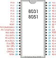
Pinagem8031.jpg 464 × 480; 122 KB
-
Pinout Notch Guide.svg 200 × 175; 356 bytes
-
Pinout PIC18F4550.png 573 × 347; 11 KB
-
Pinout Template 14 Pin.svg 200 × 200; 30 KB
-
Pinout Template 16 Pin.svg 200 × 225; 37 KB
-
Pinout Template 18 Pin.svg 200 × 250; 41 KB
-
Pinout Template 8 Pin.svg 200 × 125; 17 KB
-
Pinoutatmelavrmega8.png 468 × 512; 18 KB


