User:MichaelFrey/US253868
Jump to navigation
Jump to search
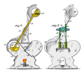
- Figure 1 represents a rear perspective view
- Fig. 2 represents a vertical section
- Fig.3 represents a front elevation, showing the pump-operating mechanism.
- A casing
- A' door
- A2 V-Shaped partition
- B lamp (or other calorific device.)
- C two standards,
- D sleeve
- E tube
- E', E2 cylindrical receptacles
- F flanged cap
- G gear-wheel
- H Racks
- I piston rods
- J pumpingcylinders
- K long rod/pitman
- L rock-shaft
- M gate
- a, a' entrances
- c, c' trunnions
- j ledge
- k crank arm
- l crank arm
