Technical drawings
Appearance
Technical drawings are drawings based on a set of conventions for the representation of object with technical purposes (design, production...).
The objects can be represented with different views (front, rear, top, bottom, left and right side). There are two ways to place the different views on the drawing:
- the European standard considers a projection on the opposite direction, like an X-ray radiography; the top view is under the front view, the right view is at the left of the front view...
- the American standard places the left view on the left and the top view on the top. like a photographic image.
The standard in use is represented by a truncated cone.
-
Penetration Sizing Guideline.
-
Plan view of Certification listing seal design UL C-AJ-8073
-
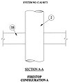
Certification listing seal design UL C-AJ-8073 Configuration A
-
listing seal design UL C-AJ-8073 Configuration B
-
Certification listing seal design UL C-AJ-8073 Configuration C
-
Certification listing seal design UL C-AJ-8073 Configuration D
-
Certification listing seal design UL C-AJ-8073 Configuration E
-
Certification listing seal design UL C-AJ-8073 Configuration F
-
Certification listing seal design UL C-AJ-8073 Configuration G


