Category:Transformer diagrams
Jump to navigation
Jump to search
Subcategories
This category has the following 4 subcategories, out of 4 total.
Media in category "Transformer diagrams"
The following 200 files are in this category, out of 419 total.
(previous page) (next page)-
2. test setups.png 670 × 146; 10 KB
-
3-fasentransformator.jpg 710 × 607; 26 KB
-
8. test setup.png 1,524 × 751; 69 KB
-
AC-DC-converter-ru.svg 446 × 276; 9 KB
-
AC-DC-converter.png 390 × 250; 2 KB
-
AC-DC-converter.svg 446 × 276; 6 KB
-
Amplistat AW-3A schemat połączeń.svg 1,110 × 1,369; 40 KB
-
Amplistat AW-3A schemat uzwojeń.svg 1,598 × 833; 64 KB
-
Amplistat-Charakterystyki.svg 729 × 599; 100 KB
-
AT Schutz Trafo.PNG 778 × 968; 66 KB
-
ATS Prinzip real.PNG 1,087 × 400; 25 KB
-
ATS Prinzip.PNG 1,061 × 737; 69 KB
-
Autotrafo02.JPG 292 × 372; 11 KB
-
Autotransformator schemat.svg 333 × 367; 35 KB
-
Autotransformer short circuit.PNG 653 × 675; 24 KB
-
Autotransformer short circuit2.PNG 653 × 675; 21 KB
-
Bauteile einer Vapour Phase Anlage.pdf 708 × 589; 617 KB
-
Caracterizar nucleo.JPG 2,048 × 1,536; 794 KB
-
Circuito magnetico simple.jpg 2,253 × 1,131; 406 KB
-
Coil In Core.jpg 1,307 × 921; 202 KB
-
Connexion etoile.png 272 × 368; 6 KB
-
Connexion triangle.png 308 × 391; 8 KB
-
Connexion zigzag.png 285 × 450; 8 KB
-
Contrainte mecanique transformateur svg.svg 509 × 530; 15 KB
-
Contrainte mecanique transformateur.png 793 × 652; 12 KB
-
Core-Stacks.jpg 427 × 779; 194 KB
-
Coupling Coefficient.gif 702 × 428; 20 KB
-
Coupling coefficient2.gif 708 × 456; 23 KB
-
D 3e harmonique svg.svg 283 × 300; 25 KB
-
D 3e harmonique.png 492 × 476; 16 KB
-
Delta-Wye Transformer.png 517 × 618; 64 KB
-
Demo transformer.png 467 × 244; 4 KB
-
Diapositiva14.PNG 960 × 720; 10 KB
-
Disc winding svg.svg 361 × 318; 19 KB
-
Disc winding.png 592 × 498; 9 KB
-
DoubleTransformerHybrid.jpg 252 × 311; 13 KB
-
Drehstromtrafo-wickelrichtung.svg 792 × 768; 263 KB
-
Dreiphasen Transformator.svg 425 × 375; 12 KB
-
DST-Zeilentrafo.png 790 × 1,379; 26 KB
-
Dy5.svg 923 × 622; 43 KB
-
Dyn5.jpg 651 × 361; 21 KB
-
E9171 - DPLA - 2c8ae6781ab341e661cbdcffc9aa6d43.jpg 5,301 × 3,700; 11.39 MB
-
EB1911 - Transformers - Fig. 3.png 989 × 502; 108 KB
-
EB1911 - Transformers - Fig. 4.png 690 × 618; 65 KB
-
EB1911 - Transformers - Fig. 5.png 631 × 357; 32 KB
-
EB1911 - Transformers - Fig. 6.png 478 × 275; 14 KB
-
EB1911 - Transformers - Fig. 7.png 625 × 392; 26 KB
-
EB1911 - Transformers - Fig. 8.png 393 × 468; 40 KB
-
EB1911 - Transformers - Fig. 9.png 627 × 853; 52 KB
-
EI-core-01.jpg 327 × 269; 39 KB
-
EI-transformer core interleaved with flux paths.png 8,656 × 3,200; 30.95 MB
-
Electrical diagram induction regulator transformer.svg 720 × 720; 14 KB
-
Electrical diagram induction regulator.svg 720 × 720; 14 KB
-
Enroulement buckling1 svg.svg 293 × 139; 16 KB
-
Enroulement buckling1.png 456 × 214; 7 KB
-
Enroulement buckling2.png 971 × 742; 68 KB
-
Enroulement canaux axiaux.png 633 × 489; 24 KB
-
Enroulement canaux radiaux svg.svg 260 × 203; 10 KB
-
Enroulement canaux radiaux.png 401 × 344; 8 KB
-
Enroulement OD.png 609 × 685; 9 KB
-
Enroulement OF svg.svg 466 × 509; 9 KB
-
Enroulement OF.png 570 × 685; 8 KB
-
Enroulement reglage helice svg.svg 408 × 648; 8 KB
-
Enroulement reglage helice.png 575 × 779; 21 KB
-
Enroulement reglage svg.svg 708 × 519; 25 KB
-
Enroulement reglage.png 1,186 × 838; 34 KB
-
Enroulement tilting svg.svg 469 × 276; 7 KB
-
Enroulement tilting.png 691 × 263; 5 KB
-
Enroulements cc svg.svg 506 × 318; 10 KB
-
Enroulements cc.png 827 × 497; 9 KB
-
Enroulements svg.svg 891 × 676; 24 KB
-
Enroulements.png 1,453 × 1,083; 56 KB
-
Ersatzschaltbild-spannungen-am-transformator-1.png 717 × 510; 14 KB
-
Ersatzschaltbild-spannungen-am-transformator-2.png 717 × 462; 13 KB
-
Ersatzschaltbild-spannungen-am-transformator-3.pdf 1,239 × 1,754; 26 KB
-
Fer doux oriente.PNG 623 × 329; 26 KB
-
Flux in two magneticaly coupled coils.png 757 × 508; 48 KB
-
Flux leakage.png 691 × 468; 48 KB
-
Foil winding svg.svg 303 × 364; 10 KB
-
Foil winding.png 497 × 592; 6 KB
-
General linear transformer.png 607 × 480; 31 KB
-
Grhwa-sbktr-hwst-14.png 862 × 425; 11 KB
-
Grupo de conexion.svg 245 × 202; 8 KB
-
Gyrator-Capacitor Model Example Three Phase Transformer.png 3,900 × 2,700; 171 KB
-
High leg delta transformer.png 648 × 717; 8 KB
-
High leg delta transformer.svg 230 × 270; 12 KB
-
HWA-weich-Tr.png 2,860 × 2,734; 441 KB
-
Hysteresekurve eines Transformatorkernes.jpg 1,226 × 947; 186 KB
-
Hystku-dauerlauf1.gif 4,498 × 3,938; 170 KB
-
Hystku-sp-str-01.png 2,157 × 2,105; 250 KB
-
Hystku-sp-str.png 4,481 × 4,161; 2.26 MB
-
Ideal transformer representation.png 1,283 × 666; 218 KB
-
Ideal transformer.png 565 × 289; 197 KB
-
Idealer Transformator.png 230 × 164; 5 KB
-
Ileerl-EIk-Ileer.png 862 × 446; 13 KB
-
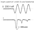
Inrush-curr-3.png 1,284 × 1,148; 16 KB
-
Interleaved winding svg.svg 362 × 318; 23 KB
-
Interleaved winding.png 592 × 498; 12 KB
-
Isolation barriere svg.svg 493 × 581; 14 KB
-
Isolation barriere.png 827 × 967; 20 KB
-
Isolation non-uniforme.png 1,406 × 716; 29 KB
-
Isolation Transformer Animation 2.gif 846 × 698; 49 KB
-
Isolation Transformer Animation.gif 846 × 698; 54 KB
-
Isolation Transformer Simple with Dielectric Barrier and Electrostatic Shield.jpg 3,151 × 3,751; 3.03 MB
-
Isolation Transformer Simple with Dielectric Barrier.jpg 3,151 × 3,451; 2.35 MB
-
Isolation Transformer Simple.jpg 3,151 × 3,601; 2.7 MB
-
Isolation Transformer with Dual Bobbins.jpg 3,676 × 3,751; 2.56 MB
-
Isolation Transformer with Split Bobbin.jpg 2,701 × 3,920; 2 MB
-
Isolation uniforme.png 1,323 × 696; 23 KB
-
Jonction svg.svg 575 × 267; 25 KB
-
Jonction.png 925 × 428; 15 KB
-
Joule thief.png 707 × 457; 17 KB
-
Joule thief.svg 826 × 595; 25 KB
-
Keringsches-parad-prim-str-sbk-mlsp.png 1,973 × 915; 33 KB
-
KHT.PNG 400 × 500; 8 KB
-
Klokgetal Dy5.jpg 364 × 376; 20 KB
-
Kompensator transformatorowy.svg 550 × 400; 35 KB
-
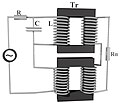
Kontur LC trans 2.jpeg 664 × 568; 33 KB
-
Kontur LC trans.jpeg 800 × 600; 55 KB
-
KonturLC-trans.png 658 × 499; 136 KB
-
Kopplungsfaktor.gif 702 × 450; 21 KB
-
Kopplungskoeffizient.gif 702 × 449; 22 KB
-
Lagenwicklung.svg 524 × 634; 33 KB
-
Laminated core eddy currents 2.svg 1,132 × 539; 23 KB
-
Laminated core eddy currents.svg 1,182 × 534; 23 KB
-
Lamination eddy currents.svg 600 × 550; 24 KB
-
Laminering av kärna.svg 445 × 546; 23 KB
-
Laminering av transformatorkärna.svg 545 × 546; 24 KB
-
Layer winding svg.svg 289 × 485; 21 KB
-
Layer winding.png 474 × 792; 11 KB
-
Leakage mesure.gif 768 × 288; 11 KB
-
Linea di distribuzione energetica.svg 600 × 230; 37 KB
-
LosslessTransformer.png 528 × 208; 3 KB
-
LosslessTransformer2.png 880 × 234; 8 KB
-
Luftspulenmessung1.png 3,095 × 1,730; 111 KB
-
Luftspulenmessung3.png 3,771 × 1,953; 884 KB
-
Lvdt how.gif 519 × 339; 8 KB
-
Magnetic coupling scheme.jpg 1,110 × 653; 58 KB
-
Magnetic flux around air-gap in transformer core made from E and I laminations.png 6,938 × 4,988; 750 KB
-
Magnetic-field-transformer-with-core.svg 800 × 600; 137 KB
-
Magnetis-luftn.png 660 × 372; 7 KB
-
Magnetkreis-berechnung-03.pdf 1,239 × 1,754; 15 KB
-
Mantelstroomtransformator.jpg 724 × 358; 32 KB
-
Maschinentransformator Schema.png 1,171 × 754; 16 KB
-
Messung der Leckage.gif 768 × 288; 12 KB
-
Messung-energiefluss-im-trafo-5.png 2,032 × 1,488; 122 KB
-
Messung-energiefluss-im-trafo-5.svg 1,052 × 744; 127 KB
-
Messung-Wickelsinn-Rktr-osc-2.png 1,403 × 3,064; 106 KB
-
Modele transformateur trois enroulements.svg 403 × 201; 31 KB
-
Mostek transformatorowy.svg 600 × 430; 54 KB
-
Máy biến thế.jpg 315 × 224; 9 KB
-
Netzstörung Trafo.svg 532 × 382; 92 KB
-
NyNTrafo.PNG 1,119 × 698; 37 KB
-
Opt transformer 2.PNG 470 × 750; 20 KB
-
PairOfCoils.png 427 × 448; 7 KB
-
Posled-rezon-trans.png 782 × 501; 107 KB
-
Power Transformer Inrush Current.gif 450 × 450; 718 KB
-
Power Transformer Maintenance and Acceptance Testing.pdf 1,302 × 1,666, 62 pages; 3.65 MB
-
Power Transformer Over-Excitation.gif 450 × 450; 795 KB
-
Princ fct trans.png 623 × 240; 32 KB
-
Prinzipdarstellung Hochstromtrafo.svg 546 × 1,141; 89 KB
-
Prinzipskizze Netzausfall.svg 620 × 616; 12 KB
-
Real transformer.png 581 × 297; 159 KB
-
Resonance Transformer.gif 432 × 240; 16 KB
-
Resonantpowertransfer.svg 400 × 150; 16 KB
-
Rktr+foen.png 512 × 512; 16 KB
-
Rktr-inr-nhwa.png 2,750 × 2,192; 7 KB
-
Rktr-Inrush-100Va.png 640 × 480; 22 KB
-
Rktr-spann-hystku-strom-3.svg 564 × 479; 62 KB
-
Rotationstrafo Schnitt de.svg 230 × 270; 11 KB
-
Rotationstrafo Schnitt.svg 230 × 270; 10 KB
-
Saturable reactor with flux lines.png 1,600 × 989; 36 KB
-
Sch princ transfo.png 588 × 275; 28 KB
-
Schaltgruppe-Zeigerbild.png 1,750 × 2,350; 408 KB
-
Schaltnetzteil-einschalten1.png 3,232 × 1,696; 75 KB
-
Scheitel-schalter-auf-trafo1.gif 2,714 × 1,798; 104 KB
-
Schema equivalent transformateur.svg 674 × 163; 26 KB
-
Schema equivalent transformateur2.svg 674 × 163; 22 KB
-
Schema Vapour Phase Trocknung, Quelle Hedrich GmbH.jpg 904 × 492; 49 KB
-
Schematic-induction regulator.svg 720 × 720; 35 KB
-
Schn-bdkern-leerl-un-41.png 862 × 446; 13 KB
-
Schnbdktr-inr-mfluss-14.png 4,094 × 2,258; 41 KB
-
Schsch auf rktr.png 3,591 × 2,053; 13 KB
-
Schsch-auf-ringktr-2.png 2,714 × 1,798; 267 KB
-
Schsch-auf-uitr.png 3,474 × 2,246; 10 KB
-
Scrapless Lam.jpg 518 × 437; 42 KB
-
Selecteur.png 1,300 × 851; 38 KB
-
Selsin Indikatornaja.png 588 × 316; 6 KB
-
Series transductor.png 1,600 × 989; 21 KB
-
Shield winding svg.svg 563 × 318; 22 KB
-
Shield winding.png 934 × 498; 11 KB
-
Shortcircuit test.svg 858 × 190; 31 KB
-
Single-phase transformer.svg 689 × 467; 70 KB
-
SingleTransformerHybrid.jpg 339 × 258; 13 KB
-
Spann-hystku-strom-2.png 439 × 619; 10 KB
-
Spann-hystku-strom-4.png 1,150 × 1,639; 29 KB
-
Spann-hystku-strom-5.png 2,723 × 4,261; 47 KB
-
Spulenmessung4.png 3,339 × 1,801; 723 KB


