Category:Shear and moment diagrams
Jump to navigation
Jump to search
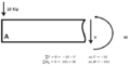
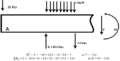
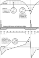
English: Shear and bending moment diagrams are analytical tools used in conjunction with structural analysis to help perform structural design by determining the value of shear force and bending moment at a given point of an element. Using these diagrams the type and size of a member of a given material can be easily determined. Another application of shear and moment diagrams is that the deflection can be easily determined using either the moment area method or the conjugate beam method.
Українська: епюри навантажень
structural design tool | |||||
| Upload media | |||||
| Subclass of | |||||
|---|---|---|---|---|---|
| |||||
Media in category "Shear and moment diagrams"
The following 16 files are in this category, out of 16 total.
-
 Diagrammes V-M 01.jpg 1,987 × 2,244; 190 KB
-
 Diagrammes V-M 02.jpg 2,451 × 2,595; 406 KB
-
 Section 1.PNG 591 × 293; 12 KB
-
 Section 2.PNG 677 × 370; 17 KB
-
 Section 3.PNG 698 × 363; 18 KB
-
 Section 4.PNG 695 × 342; 19 KB
-
 Section Four.PNG 667 × 341; 19 KB
-
 Section One.PNG 573 × 289; 11 KB
-
 Section Three.PNG 683 × 346; 18 KB
-
 Section Two.PNG 691 × 369; 18 KB
-
 Shear Moment Diagram.svg 431 × 265; 18 KB
-
 Shear Partitioning Mechanism.png 3,165 × 2,482; 203 KB
-
 Stahlbeton-Bodenplatte-Prinzip.svg 465 × 693; 74 KB
-
 정정 프레임2.png 1,209 × 646; 12 KB
-
 정정 프레임4.png 1,066 × 581; 10 KB
-
 정정 프레임5.png 1,194 × 585; 14 KB


