Category:Relay circuits
Jump to navigation
Jump to search
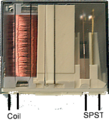
English: Are circuits to operate high-voltage or high-current circuits through low currrent and safe for human voltage. Widespreadly complex relay circuits are used in automation. Example of simple relay circuit you can see here.
Subcategories
This category has the following 3 subcategories, out of 3 total.
Media in category "Relay circuits"
The following 60 files are in this category, out of 60 total.
-
3-way light switch using relay.JPG 760 × 420; 27 KB
-
8226 relays.JPG 1,024 × 768; 140 KB
-
Analogue memory relay.JPG 490 × 329; 25 KB
-
AND-poort relais.png 196 × 214; 2 KB
-
Arcor-DSL Speed-Modem 200 - UT TBS-5VDC-C20-S1-92487.jpg 4,112 × 2,313; 5.24 MB
-
Battery-powered preamp - power management (as built).jpg 3,000 × 1,500; 1.52 MB
-
Battery-powered preamp - power management (UVLO, muting delay).png 2,118 × 948; 231 KB
-
Battery-powered preamp - power management.png 2,199 × 1,345; 238 KB
-
Circuit diagram of logarithmic ladder DA converter, Mar 2012.png 877 × 200; 3 KB
-
Double switched.svg 320 × 150; 17 KB
-
DPDT relay symbol.svg 86 × 89; 8 KB
-
Dusk relay for dummies (FL).JPG 1,500 × 975; 115 KB
-
Dusk relay for dummies.JPG 1,840 × 750; 108 KB
-
Economy muting relay coil drive for 30V-powered (opamp-based) devices.png 1,268 × 1,086; 122 KB
-
Economy relay coil drive for battery-powered devices (simplest - series RC).png 1,415 × 1,129; 112 KB
-
Economy relay coil drive for battery-powered devices (ULN2003A).png 1,916 × 1,062; 160 KB
-
Economy relay coil drive for battery-powered devices.png 2,258 × 879; 86 KB
-
Einschaltverzögerung.png 236 × 140; 2 KB
-
Electronic phase control relay.jpg 537 × 511; 54 KB
-
Memory relay.JPG 870 × 360; 39 KB
-
Multiway switching.JPG 1,000 × 360; 40 KB
-
NOT-poort relais.png 174 × 111; 835 bytes
-
PanasonicDS4E-S-DC5VRelay.jpg 274 × 152; 21 KB
-
Phases control by relays.jpg 1,740 × 1,670; 165 KB
-
Principial wiring diagram of shined day automatics.JPG 360 × 300; 19 KB
-
Relais induktivität.svg 300 × 225; 8 KB
-
Relais schalten.jpg 867 × 695; 42 KB
-
Relais-Finder-12A.webm 6.1 s, 1,920 × 1,080; 2.47 MB
-
RelaisdiagrammBeispiel.svg 142 × 213; 76 KB
-
RelaisdiagrammSymbolik.png 397 × 265; 12 KB
-
RelaisdiagrammSymbolik.svg 372 × 213; 12 KB
-
Relaissteuerung1 hg.jpg 4,878 × 3,280; 2.5 MB
-
Relay 2.jpg 4,032 × 3,024; 2.96 MB
-
Relay example.jpg 315 × 249; 22 KB
-
Relay switches.jpg 1,454 × 1,499; 270 KB
-
Relay symbols.svg 309 × 453; 40 KB
-
RelayArduinoTest.jpg 2,856 × 2,932; 1.51 MB
-
RelaydiagramExample.svg 142 × 213; 79 KB
-
RelayHelishunHLST90.jpg 2,665 × 1,998; 3.02 MB
-
Rele1.jpeg 341 × 189; 5 KB
-
Schutzbeschaltung-diode.svg 600 × 400; 13 KB
-
Schutzbeschaltung-rc-glied.svg 600 × 400; 19 KB
-
Schutzbeschaltung-vdr.svg 600 × 400; 17 KB
-
Schutzbeschaltung-widerstand.svg 600 × 400; 14 KB
-
Schutzbeschaltung-z-diode.svg 600 × 400; 15 KB
-
Simplified wiring diagram of night-day relay.JPG 1,100 × 330; 50 KB
-
Single switching.svg 320 × 150; 16 KB
-
SPDT relay symbol.svg 74 × 89; 7 KB
-
SPST-NO relay symbol.svg 78 × 110; 6 KB
-
Spst-relay.png 226 × 249; 109 KB
-
Sw relay.JPG 1,050 × 650; 58 KB
-
Symbole Contacteur.png 241 × 98; 1 KB
-
Wiring diagram of time relay.JPG 2,160 × 700; 112 KB
-
Wiring up a Relay oscillator on a breadboard .jpg 4,928 × 3,264; 930 KB
-
Схема замедления 1.png 205 × 45; 1 KB
-
Схема замедления 2.png 208 × 102; 2 KB
-
Схема замедления 3.png 208 × 103; 3 KB
-
Схема замедления 4.png 205 × 46; 1 KB
-
Схема замедления 5.png 205 × 77; 2 KB
-
Схема замедления 6.png 205 × 48; 1 KB


