Category:Pilot's Handbook of Aeronautical Knowledge
Jump to navigation
Jump to search
This image or file is a work of a Federal Aviation Administration employee, taken or made as part of that person's official duties. As a work of the U.S. federal government, the image is in the public domain in the United States.
|
 |
Media in category "Pilot's Handbook of Aeronautical Knowledge"
The following 85 files are in this category, out of 85 total.
-
 Absolute and service ceiling of an aircraft.png 1,356 × 1,328; 453 KB
-
 Absolute and Service Ceilings.jpg 630 × 615; 114 KB
-
 AC 61-23C Fig 03-08.png 675 × 228; 66 KB
-
 Adjustable stabilizer.svg 294 × 171; 110 KB
-
 AHRS.png 494 × 413; 97 KB
-
 AI aircraft orientation.png 966 × 865; 339 KB
-
 Aircraft electrical system schematic.png 1,894 × 2,142; 1.67 MB
-
 Aircraft propeller twist.png 1,750 × 856; 482 KB
-
 Airfield wind direction indicators.png 1,954 × 862; 1.56 MB
-
 Airplane major components.png 2,184 × 1,434; 1.13 MB
-
 Airport Directory sample.PNG 794 × 693; 231 KB
-
 Airspeed indicator interior-it.svg 314 × 267; 316 KB
-
 Airspeed indicator interior.svg 314 × 267; 274 KB
-
 Airspeed-indicator-FAA.PNG 235 × 236; 107 KB
-
 AngleOfClimb.jpg 1,287 × 484; 85 KB
-
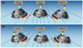
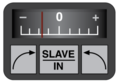
 AOA Indicators.png 1,312 × 453; 537 KB
-
 Area Forecast Region Map.png 3,162 × 2,098; 2.94 MB
-
 ASI TrendVector.png 792 × 640; 59 KB
-
 ASI-operation-FAA PT.svg 512 × 310; 4.43 MB
-
 ASI-operation-FAA.png 354 × 197; 33 KB
-
 ASI.png 785 × 668; 165 KB
-
 Attitude Indicator Interior.png 913 × 759; 201 KB
-
 Automatic direction finder with fixed azimuth and magnetic compass.png 1,334 × 1,222; 1.69 MB
-
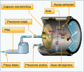
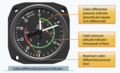 Cabin or differential pressure indicator.png 1,496 × 910; 463 KB
-
 Carburetor components.png 3,402 × 2,102; 2.71 MB
-
 Carburetor icing conditions.png 785 × 532; 119 KB
-
 Carburetor Icing diagram.png 472 × 583; 121 KB
-
 CG moment envelope.png 2,558 × 1,762; 659 KB
-
 Coefficients of Drag and Lift vs AOA.jpg 920 × 580; 132 KB
-
 Comparison of normal and distorted airflow into the compressor section.png 2,040 × 1,480; 955 KB
-
 Compass correction card.png 2,390 × 946; 731 KB
-
 Compass rose.png 340 × 345; 72 KB
-
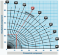 Crosswind component chart.png 1,368 × 1,286; 641 KB
-
 Deicing boots on the leading edge of the wing.png 1,550 × 2,072; 1.98 MB
-
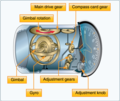 DG interior.png 818 × 688; 218 KB
-
 Diagram of an EMASMAX system.png 1,830 × 1,818; 395 KB
-
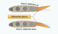 Differential ailerons.png 1,930 × 1,124; 502 KB
-
 DragvsSpeed.jpg 943 × 569; 107 KB
-
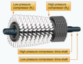 Dual-spool axial-flow compressor.png 2,638 × 2,048; 2.52 MB
-
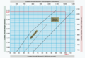
 Effect of altitude on range at a constant weight.png 2,232 × 1,798; 534 KB
-
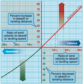 Effect of wind on takeoff and landing.png 1,932 × 1,968; 923 KB
-
 Elevator trim tab movement.png 1,308 × 1,494; 691 KB
-
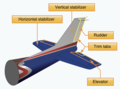 Empennage components.png 1,860 × 1,376; 623 KB
-
 Entering traffic pattern - Alternate Midfield Entry.png 1,222 × 1,684; 1.51 MB
-
 Entering traffic pattern - Preferred Entry-Crossing Midfield.png 1,380 × 1,900; 2.11 MB
-
 Faa altimeter.JPG 438 × 388; 32 KB
-
 FAA PHAK 2008 Fig 16-5 Graveyard spiral.png 1,280 × 988; 228 KB
-
 Faa pitot static system.JPG 438 × 281; 22 KB
-
 Faa vertical air speed.JPG 339 × 297; 22 KB
-
 Faavspeedsonairspeedind.PNG 475 × 358; 88 KB
-
 Flux valve in use, Fluxgate Compass System.png 1,632 × 1,002; 943 KB
-
 Flux valve sections, Fluxgate Compass System.png 1,630 × 1,712; 1.14 MB
-
 Frise-type ailerons.png 1,440 × 1,618; 877 KB
-
 Fuselage and fin for directional stability.png 992 × 1,136; 524 KB
-
 Gravity-feed and fuel-pump systems.png 946 × 1,812; 870 KB
-
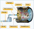
 High performance airplane pressurization system.png 1,198 × 1,794; 895 KB
-

-
 Hydromechanical flight control system.png 1,360 × 926; 549 KB
-
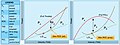
 Maximum Endurance and Range.jpg 1,292 × 473; 153 KB
-
 Monocoque fuselage design.png 1,222 × 664; 309 KB
-
 Night blind spot.png 1,116 × 1,442; 942 KB
-
 Northerly and southerly turning errors.png 2,608 × 1,494; 1.82 MB
-
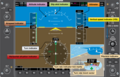 PFD.png 1,149 × 737; 242 KB
-
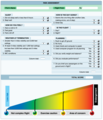 Pilot Risk Assessment.png 1,598 × 1,860; 716 KB
-
 Propeller blade AOA versus pitch.png 1,109 × 704; 162 KB
-
 Propeller blade AOA.png 1,094 × 648; 117 KB
-
 Pulsating visual approach slope indicator.png 3,318 × 952; 1.71 MB
-
 RateOfClimb.jpg 1,285 × 484; 90 KB
-
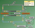
 Remote indicating compass magnetic slaving transmitter.png 2,350 × 1,438; 1.09 MB
-
 Remote indicating compass slaving control and compensator unit.png 2,088 × 1,442; 584 KB
-
 Runway incursion.png 1,036 × 778; 668 KB
-
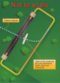
 Runway Safety Area.png 2,726 × 1,718; 667 KB
-
 Segmented circle visual indicator system for traffic pattern.png 1,272 × 1,262; 1.56 MB
-
 Semimonocoque fuselage design.png 1,222 × 658; 342 KB
-
 Temperature's influence on aircraft altimeters.png 1,702 × 960; 240 KB
-
 Traffic patterns depicted in FAA-H-8083-25.jpg 1,293 × 1,055; 228 KB
-
 Transponder Radar Beacon Phraseology.png 2,776 × 1,686; 534 KB
-
 Tri-color visual approach slope indicator.png 2,598 × 744; 522 KB
-
 Truss-type fuselage structure.png 1,854 × 1,934; 1.22 MB
-
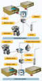
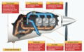 Turbosuperchargers.png 3,022 × 1,874; 2.17 MB
-
 Turninst.jpg 515 × 654; 173 KB
-
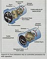 Turninst4.jpg 515 × 654; 188 KB
-
 Vacuum Pump system.png 1,480 × 744; 236 KB
-
 Vgdiagram.jpg 970 × 646; 132 KB
-
 Wing Components.png 2,488 × 1,408; 1.34 MB


_critical_area_boundary.png)


