Category:Eawag
Jump to navigation
Jump to search
Swiss federal research institute   | |||||
| Upload media | |||||
| Instance of | |||||
|---|---|---|---|---|---|
| Location | Dübendorf, Uster District, Canton of Zürich, Switzerland | ||||
| Item operated |
| ||||
| Inception |
| ||||
| official website | |||||
 | |||||
Media in category "Eawag"
The following 124 files are in this category, out of 124 total.
-
 Activated Sludge diagram fr.svg 449 × 276; 340 KB
-
 Activated Sludge diagram.svg 730 × 423; 182 KB
-
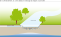
 Aerated Pond diagram fr.svg 452 × 276; 273 KB
-
 Aerated Pond diagram.svg 730 × 423; 108 KB
-
 Anaerobic Baffled Reactor ABR diagram fr.svg 449 × 276; 747 KB
-
 Anaerobic Baffled Reactor ABR diagram.svg 730 × 423; 534 KB
-
 Anaerobic Filter diagram fr.svg 449 × 276; 725 KB
-
 Anaerobic Filter diagram.svg 730 × 423; 465 KB
-
 Application of Dehydrated Faeces diagram fr.svg 449 × 276; 256 KB
-
 Application of Dehydrated Faeces diagram.svg 730 × 423; 81 KB
-
 Application of Sludge diagram fr.svg 449 × 278; 1.88 MB
-
 Application of Sludge diagram.svg 730 × 423; 715 KB
-
 Biogas Combustion diagram fr.svg 449 × 277; 315 KB
-
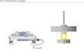
 Biogas Combustion diagram.svg 730 × 423; 17 KB
-
 Biogas Reactor diagram fr.svg 451 × 276; 269 KB
-
 Biogas Reactor diagram.svg 730 × 423; 142 KB
-
 Chriesbach – Dübendorf EAWAG.jpg 4,032 × 3,024; 4.45 MB
-
 Christian Zurbrugg (EAWAG- SANDEC) talking to the crowd (15349506107).jpg 2,304 × 3,456; 2.84 MB
-
 Cistern Flush Toilet diagram fr.svg 449 × 287; 256 KB
-
 Cistern Flush Toilet diagram.svg 730 × 423; 23 KB
-
 Co-Compost diagram fr.svg 449 × 276; 310 KB
-
 Co-Compost diagram.svg 730 × 423; 446 KB
-
 Composting Chamber diagram fr.svg 449 × 276; 991 KB
-
 Composting Chamber diagram.svg 730 × 423; 807 KB
-
 Conventional Gravity Sewer diagram fr.svg 492 × 278; 1.06 MB
-
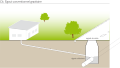
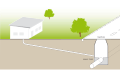 Conventional Gravity Sewer diagram.svg 730 × 423; 427 KB
-
 Dehydration Vaults diagram fr.svg 449 × 278; 348 KB
-
 Disinfection and Tertiary Filtration diagram fr.svg 449 × 276; 1.48 MB
-
 Disinfection and Tertiary Filtration diagram.svg 730 × 423; 662 KB
-
 Display set-up for evaporation of nitrified urine (5363685574).jpg 3,584 × 2,688; 2.33 MB
-
 Double Ventilated Improved Pit diagram fr.svg 449 × 281; 300 KB
-
 Double Ventilated Improved Pit diagram.svg 730 × 423; 108 KB
-
 Dry Toilet diagram fr.svg 449 × 277; 218 KB
-
 Eawag Dübendorf, Forum Chriesbach.jpg 2,000 × 1,500; 769 KB
-
 Eawag Kastanienbaum.jpg 1,600 × 1,200; 1.01 MB
-
 Eawag-Brücke über den Chriesbach, Dübendorf ZH 20220421-jag9889.jpg 4,608 × 3,456; 13.9 MB
-
 FC Atrium 2.JPG 4,912 × 7,360; 8.52 MB
-
 FC Atrium.jpg 6,403 × 4,273; 10.44 MB
-
 FC im Winter 01.JPG 7,360 × 4,912; 8.74 MB
-
 Fig 6 - EAWAG - struvite reactor - Nepal (6519920831).jpg 526 × 524; 38 KB
-
 Fill and Cover Arborloo diagram fr.svg 449 × 276; 664 KB
-
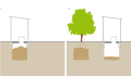 Fill and Cover Arborloo diagram.svg 730 × 423; 296 KB
-
 Fish Pond (Aquaculture) diagram fr.svg 450 × 276; 237 KB
-
 Fish Pond (Aquaculture) diagram.svg 730 × 423; 70 KB
-
 Floating Plant Pond diagram fr.svg 450 × 276; 454 KB
-
 Floating Plant Pond diagram.svg 730 × 423; 258 KB
-
 Fossa Alterna diagram fr.svg 449 × 277; 674 KB
-
 Fossa Alterna diagram.svg 730 × 423; 431 KB
-
 Free Water Surface Constructed Wetland diagram fr.svg 449 × 276; 351 KB
-
 Free Water Surface Constructed Wetland diagram.svg 730 × 423; 185 KB
-
 Horizontal Subsurface Flow Constructed Wetland diagram fr.svg 449 × 276; 519 KB
-
 Horizontal Subsurface Flow Constructed Wetland diagram.svg 730 × 423; 367 KB
-
 Human-Powered Emptying and Transport diagram fr.svg 463 × 263; 296 KB
-
 Human-Powered Emptying and Transport diagram.svg 730 × 423; 109 KB
-
 Imhoff Tank diagram fr.svg 449 × 280; 396 KB
-
 Imhoff Tank diagram.svg 730 × 423; 631 KB
-
 Leach field diagram fr.svg 449 × 276; 259 KB
-
 Leach field diagram.svg 730 × 423; 112 KB
-
 Logo Eawag.svg 400 × 100; 22 KB
-
 Logo Oekotoxzentrum.svg 400 × 100; 19 KB
-
 Magalie Bassan (EAWAG) (6921836019).jpg 3,240 × 4,320; 2.68 MB
-
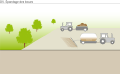
 Motorised Emptying and Transport diagram fr.svg 449 × 276; 228 KB
-
 Motorised Emptying and Transport diagram.svg 730 × 423; 51 KB
-
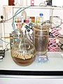 Nitrification of urine (5363685748).jpg 2,688 × 3,584; 2.27 MB
-
 Pictogrammes SODIS.svg 512 × 141; 33 KB
-
 Pictograms SODIS.jpg 1,024 × 281; 143 KB
-
 Pit toilet cropped.png 815 × 610; 27 KB
-
 Planted Drying Beds diagram fr.svg 449 × 276; 547 KB
-
 Planted Drying Beds diagram.svg 730 × 423; 359 KB
-
 Pour-flush Toilet diagram fr.svg 449 × 301; 230 KB
-
 Pour-flush Toilet diagram.svg 730 × 423; 12 KB
-
 Pre-Treatment Technologies diagram fr.svg 449 × 276; 544 KB
-
 Pre-Treatment Technologies diagram.svg 730 × 423; 435 KB
-
 Schematic of a composting chamber.png 1,000 × 579; 112 KB
-
 Schematic of the Biogas Reactor-el.png 913 × 529; 93 KB
-
 Schematic of the Biogas Reactor.jpg 730 × 423; 43 KB
-
 Schematic of the Conventional Gravity Sewer.jpg 730 × 423; 58 KB
-
 Schematic of the Free Water Surface Constructed Wetland eestik.jpg 730 × 423; 47 KB
-
 Schematic of the Free Water Surface Constructed Wetland.jpg 730 × 423; 64 KB
-
 Schematic of the Simplified Sewer.jpg 730 × 423; 58 KB
-
 Schematic of the Solids Free Sewer.jpg 730 × 423; 62 KB
-
 Schematic of the Waste Stabilization Pond (WSP).jpg 730 × 423; 78 KB
-
 Sedimentation Thickening Ponds diagram fr.svg 449 × 276; 754 KB
-
 Sedimentation Thickening Ponds diagram.svg 730 × 423; 543 KB
-
 Septic tank diagram fr.svg 449 × 276; 858 KB
-
 Settler diagram fr.svg 449 × 278; 536 KB
-
 Settler diagram.svg 730 × 423; 320 KB
-
 Simplified Sewer diagram fr.svg 449 × 278; 1.45 MB
-
 Simplified Sewer diagram.svg 730 × 423; 595 KB
-
 Single pit diagram fr.svg 449 × 276; 218 KB
-
 Single Ventilated Improved Pit diagram fr.svg 454 × 276; 264 KB
-
 Single Ventilated Improved Pit diagram.svg 730 × 423; 71 KB
-
 Soak Pit diagram fr.svg 449 × 276; 245 KB
-
 Soak Pit diagram.svg 730 × 423; 52 KB
-
 Solids Free Sewer diagram fr.svg 449 × 278; 1.06 MB
-
 Solids Free Sewer diagram.svg 730 × 423; 502 KB
-
 Surface Disposal and Storage diagram fr.svg 449 × 276; 1.45 MB
-
 Surface Disposal and Storage diagram.svg 730 × 423; 506 KB
-
 Tilley et al 2014 Schematic of the Dry Toilet.svg 730 × 423; 46 KB
-
 Tilley et al 2014 Schematic of the Single Pit.svg 730 × 423; 48 KB
-
 Transfer Station diagram fr.svg 449 × 276; 249 KB
-
 Transfer Station diagram.svg 730 × 423; 116 KB
-
 Trickling Filter diagram fr.svg 449 × 285; 773 KB
-
 Trickling Filter diagram.svg 730 × 423; 462 KB
-
 Twin Pits for Pour Flush diagram fr.svg 456 × 277; 298 KB
-
 Twin Pits for Pour Flush diagram.svg 730 × 423; 163 KB
-
 Unplanted Drying Beds diagram fr.svg 449 × 276; 420 KB
-
 Unplanted Drying Beds diagram.svg 730 × 423; 215 KB
-
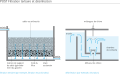
 Upflow Anaerobic Sludge Blanket Reactor UASB diagram fr.svg 449 × 254; 339 KB
-
 Upflow Anaerobic Sludge Blanket Reactor UASB diagram.svg 730 × 423; 173 KB
-
 Urinal diagram fr.svg 450 × 277; 205 KB
-
 Urinal diagram.svg 730 × 423; 6 KB
-
 Urine Diverting Dry Toilet diagram fr.svg 452 × 287; 325 KB
-
 Urine Diverting Dry Toilet diagram.svg 730 × 423; 12 KB
-
 Urine Storage Tank diagram fr.svg 449 × 276; 221 KB
-
 Urine Storage Tank diagram.svg 730 × 423; 11 KB
-
 Urine-Diverting Flush Toilet diagram fr.svg 449 × 277; 228 KB
-
 Urine-Diverting Flush Toilet diagram.svg 730 × 423; 26 KB
-
 Vertical Flow Constructed Wetland diagram fr.svg 449 × 276; 519 KB
-
 Vertical Flow Constructed Wetland diagram.svg 730 × 423; 401 KB
-
 Waste Stabilization Pond diagram fr.svg 450 × 276; 368 KB
-
 Waste Stabilization Pond diagram.svg 730 × 423; 278 KB
-
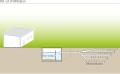
 Water Disposal and Groundwater Recharge diagram fr.svg 449 × 276; 1.51 MB
-
 Water Disposal and Groundwater Recharge diagram.svg 730 × 423; 696 KB


_talking_to_the_crowd_(15349506107).jpg)


.jpg)


.jpg)


_diagram_fr.svg)
_diagram.svg)


_(6921836019).jpg)
.jpg)


.jpg)


