Category:Heat pump diagrams
Jump to navigation
Jump to search
refrigeration process | |||||
| Upload media | |||||
| Subclass of | |||||
|---|---|---|---|---|---|
| |||||
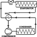
Diagrams of phase-change heat pumps
Media in category "Heat pump diagrams"
The following 70 files are in this category, out of 70 total.
-
Absorbtion.png 1,772 × 338; 36 KB
-
Absorption cooling.png 568 × 856; 26 KB
-
Absorption heat pump configuration (refrigeration).jpg 837 × 507; 51 KB
-
Absorption heat pumps type 1.jpg 387 × 338; 18 KB
-
Absorption refrigerator working.svg 816 × 889; 527 KB
-
Absorptionswaermepumpe Typ1.png 1,040 × 720; 60 KB
-
Absorptionswaermepumpe Typ2.png 1,040 × 720; 62 KB
-
Brüdenkompression.svg 930 × 1,252; 40 KB
-
Chauffage.svg 442 × 270; 34 KB
-
Circuit frigorifique de base.JPG 535 × 423; 75 KB
-
Circuit frigorifique.svg 601 × 475; 344 KB
-
Circuit heatpump.png 718 × 507; 28 KB
-
Circuit pompe à chaleur à air.svg 898 × 567; 25 KB
-
Circuit warmtepomp.svg 694 × 468; 50 KB
-
Coils (def 4 and 5) (PSF).jpg 958 × 528; 51 KB
-
Compression-Absorption Heat Transformer Mech-Powered Osenbrück Cycle.png 1,028 × 934; 635 KB
-
Cooling coil (PSF).jpg 405 × 528; 32 KB
-
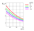
Cop temp.JPG 530 × 539; 32 KB
-
Cop-example-hp.svg 257 × 198; 24 KB
-
Countercurrent accumulator.svg 512 × 146; 30 KB
-
Countercurrent conservator.svg 512 × 173; 26 KB
-
Countercurrent furnace.svg 512 × 144; 29 KB
-
Courbes-de-chauffe-PAC.jpg 1,276 × 1,755; 253 KB
-
Cycle heat bg.jpg 500 × 373; 89 KB
-
Diagram1234321.png 772 × 777; 42 KB
-
Flash Gas Common Causes.png 275 × 302; 36 KB
-
Gasturbine-Warmtepomp.svg 744 × 524; 42 KB
-
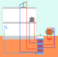
Heat pump system on rainwater pit.png 442 × 436; 6 KB
-
Heatpump.svg 750 × 438; 34 KB
-
Heatpump2.svg 715 × 367; 74 KB
-
HeatpumpCOP.svg 1,000 × 900; 19 KB
-
Koelemiddelkurve (ro).png 550 × 330; 9 KB
-
Koelemiddelkurve.gif 590 × 315; 8 KB
-
Kompressorkuehlschrank.svg 624 × 718; 42 KB
-
Log ph Diagram.png 1,788 × 959; 171 KB
-
Modélisation frigo 1.jpg 557 × 141; 21 KB
-
Modélisation frigo 2.jpg 521 × 194; 26 KB
-
Phase change heat pump.png 520 × 300; 19 KB
-
Phase change heat pump.svg 520 × 300; 15 KB
-
PompeAchaleur.png 750 × 438; 44 KB
-
PompeHopHop.jpg 919 × 1,022; 62 KB
-
Pop-Hop-2.jpg 1,255 × 934; 93 KB
-
Pop-Hop.jpg 1,237 × 1,033; 100 KB
-
Pump v5.gif 768 × 401; 1.38 MB
-
Pumpeprosess (ro).jpg 1,100 × 700; 189 KB
-
Pumpeprosess.JPG 1,118 × 707; 183 KB
-
PVdiagram.xcf 888 × 596; 129 KB
-
PVdiagramm.xcf 888 × 596; 126 KB
-
Q-otto-cycle.pdf 1,189 × 883; 79 KB
-
R407C eng.PNG 428 × 624; 18 KB
-
R407C lin.png 428 × 624; 18 KB
-
Refrigerator-cycle (ro).svg 650 × 460; 54 KB
-
Refrigerator-cycle.svg 650 × 460; 54 KB
-
Refrigerator-cycle1.svg 1,200 × 1,300; 24 KB
-
Schéma énergétique d'une pompe à chaleur.png 631 × 502; 41 KB
-
Series Operated Solar Heat Pump diagram.svg 4,606 × 5,669; 57 KB
-
StoddardEnginePatentDrawing1919.jpg 629 × 843; 83 KB
-
Vapor Compression Cycle.png 1,220 × 1,000; 91 KB
-
Varmepump.JPG 439 × 222; 18 KB
-
Warmtepomp circuit.png 725 × 522; 39 KB
-
Warmtepomp-schema.svg 372 × 524; 32 KB
-
Werking warmtepomp.jpg 1,095 × 357; 67 KB
-
Werking warmtepomppaneelsysteem.jpg 846 × 517; 65 KB
-
WP-Schaltbild-.jpg 834 × 748; 59 KB
-
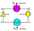
WP-Schaltbild.jpg 834 × 748; 98 KB
-
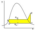
WP-T-s-Dia.jpg 857 × 729; 64 KB
-
Wärmepumpe.jpg 1,011 × 413; 138 KB
-
Обратен цикъл на Карно.jpg 500 × 269; 36 KB
-
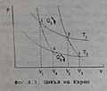
Цикъл на Карно p v diagram.jpg 270 × 229; 17 KB


